3D printed 4x5 photo paper tools
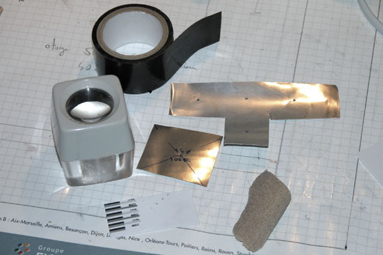
Photo paper cutter stencil and mask for scanning
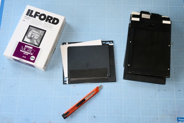
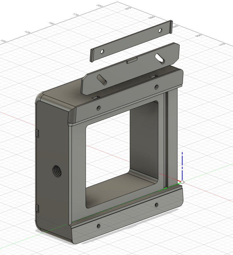
These are two tools I designed to help with with pinhole photography on photo paper with 4x5 filmholders, for cutting and scanning.
3D printed pinhole on Mamiya RB67 film holder
I just finished printing my pinhole camera for Mamiya RB67 film holder. It has some nice features: good fixation system for the back, front panel compatible with graflex lens board, so that I can use the custon pinhole board I already made. Now I should try to print it in two parts, it will be more convenient. I am thinking of using wood as the main body, with only the back end front in PLA. It will be nicer and more modular.
3D printed parametric lens board
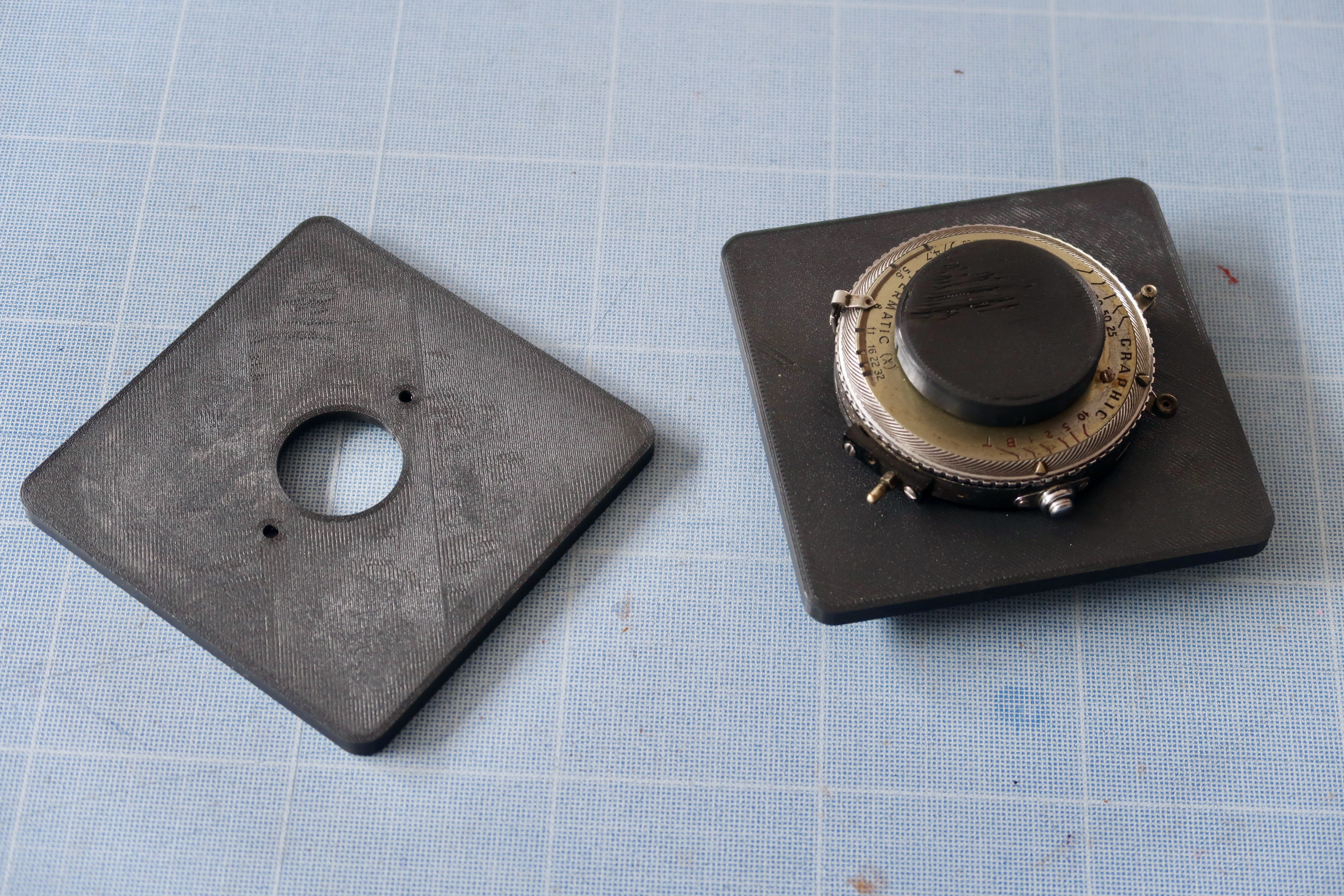
There is a lot of crown graphic graflex lens boards on thingiverse, so I made another one 🙂 . I have differents lens : a kodak, a home made protrait lens, pinholes. I wanted a parametric design that allow different hole size, notches (for positionning the kodak lens), fixation holes (for the pinhole and homemade). Done with OpenSCAD.
3D printed parametric lens cap
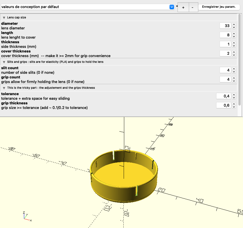
I made some lens caps for my old cameras. A foca (french camera from the 50s) and my grapflex. They have some slits for elasticity and some grips inside. I made them with PLA, but I should try PETG for more elasticity. I usec openScad for parametric design.
Bluetooth Mouse 2 Keyboard [updated]
This project allows a BLE 5Bluetooth Low energy) mouse movement to be converted in keyboard arrow movements.
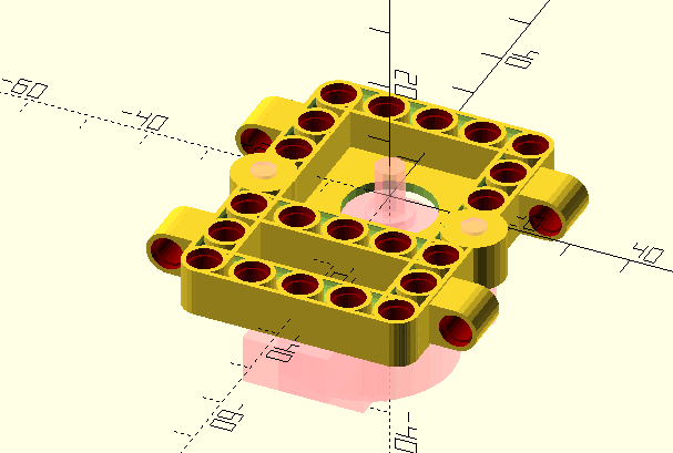
3D printed lego part for holding step motor and servo
Here are two lego parts designed for adapting servos an stepper motors to the Lego system.
Quelques recettes et ficelles pour débuter au sténopé
Il existe déjà multitude de sites en français et en anglais sur la construction du sténopé. Plutôt que de les dupliquer plus ou moins bien, cette page vient en complément de ces sites en précisant des points que j’avais trouvé peu clair quand j’ai débuté.
![image from Bluetooth Mouse 2 Keyboard [updated]](/blog/2024-bluetoothmouse2keyboard/images/image_1.png)
